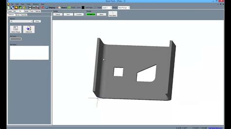
sheet metal freecad Easy to follow Step-By-Step Tutorial on how to create Sheet Metal models using the FreeCAD Sheet Metal Workbench.Published by 321 Step-By-Step Tutorials. Contact the team at Williams Metal Fabrications today to discuss options for your custom metal fabrication, design or installation project in South Australia.
0 · sheet metal software free download
1 · sheet metal bending software free
2 · freecad sheet metal workbench
3 · freecad sheet metal download
4 · free sheet metal templates
5 · free sheet metal layout software
6 · free sheet metal layout patterns
7 · free cad software for metalworking
Buy great products from our conduit box Category online at Wickes.co.uk. We supply trade quality DIY and home improvement products at great low prices.
sheet metal software free download
extendable curtain rod bracket gun metal
SheetMetal is an external workbenchand does not belong to the standard FreeCAD installation. It has been developed to supply tools to create and unfold sheet metal objects. Characteristics of sheet metal objects are: 1. They have a constant thickness 2. They can be unfolded, if they are made of planar walls and . See moreThis workbench can be installed from the Addon Manager. For manual installation see Installing more workbenches. See moreThis workbench provides tools for the two main tasks: 1. Create sheet metal objects 2. Unfold sheet metal objects This section is meant to give a rough idea of how to use the supplied tools. More detailed information can be found on each tool's own page (see . See more Easy to follow Step-By-Step Tutorial on how to create Sheet Metal models using the FreeCAD Sheet Metal Workbench.Published by 321 Step-By-Step Tutorials.
A simple sheet metal workbench for FreeCAD. Contribute to shaise/FreeCAD_SheetMetal development by creating an account on GitHub.
The SheetMetal workbench (an external workbench available through the Addon Manager) has grown quite powerful and merits to be appropriately documented. To avoid the overcrowding of the tool pages with . In this lesson you will see the introduction to sheet metal workbench based on example of creation the 3D model of holed. #freecadtutorial #freecad #freecaddesign In this video I have explained Basic of Sheet Metal Design in FreeCAD. ️ Visit my website for more info on FreeCAD-:. This tutorial is designed for beginner level FreeCAD user. In this tutorial I have covered basics of Sheet Metal Workbench like sheet metal thickness, Bending Radius, Flange .
how to use freecad free sheet metal design software sheet metal cad freecad sheet metal for beginners ad pcbway 3dparts4u allvisuals4u: Like. Share Share this awesome .
Sheet metal needs A LOT of work. In some ways it is quite good already, for example being able to generate an entire 8 bend box with one feature. But then there is the 3rd dimension of sheet metal - the formed features, the workflow . Discover the top 5 free CAD software for sheet metal design, including FreeCAD, Onshape, and Fusion 360. Unleash your creativity with these powerful, easy-to-use programs that streamline your sheet metal projects.Description. La commande SheetMetal Rebord crée des rebords sur les bords sélectionnés d'une plaque de base. En modifiant la propriété Données angle d'un rebord, on peut le transformer en bord rabattu.. Un bord est constitué d'un .
sheet metal bending software free
Description. La commande SheetMetal Plier une tôle plie une tôle (brute) selon une ligne choisie.. Elle peut être utilisée avec une plaque prédécoupée pour créer une zone de pliage perforée; laisser des sections planes dans la zone de .A Fold object is the result of a sheet metal plate bent at a given line. Change the property Daten Position to control where the bend is positioned according to the bend line. Cross-section of the bend: The bend line lies on the upper face of . Description. The SheetMetal Unfold command unfolds a sheet metal object.. Usage. Select a planar face of the sheet metal part. Activate the Unfold command using one of the following: . The Unfold button.; The SheetMetal → Unfold menu option.; The keyboard shortcut: U. Adjust unfolding options in the task panel by: . Selecting the projection options of .Introduzione. Sheet Metal è un ambiente esterno e non appartiene all'installazione standard di FreeCAD. È stato sviluppato per fornire strumenti per realizzare e dispiegare oggetti in lamiera.. Le caratteristiche degli oggetti in lamiera sono: Hanno uno spessore costante; Possono essere dispiegati, se sono fatti solo di pareti piane e connessioni cilindriche
The Sketch On Sheet metal command cuts holes along the folded walls of a sheet metal object. For the hole layout a sketch is used. In contrast to the PartDesign Pocket command, where holes are just cut along the sketch normal (local z axis), this tool acts as if it would unfold the sheet metal object, cut the holes, and refold the object. Usage
From FreeCAD Documentation. This page is a translated version of the page SheetMetal Unfold and the translation is 100% complete. Diese Dokumentation ist noch nicht fertiggestellt. Bitte hilf mit und trage etwas zur Dokumentation bei. Die Seite GuiBefehl Modell erklärt, wie Befehle dokumentiert werden sollten. Post here for help on using FreeCAD's graphical user interface (GUI). Forum rules and Helpful information. IMPORTANT: Please click here and read this first, before asking for help . I'm working on a sheet metal part, but where a bend will work or won't work is a complete mystery to me. It's been a few weeks, but I haven't yet gotten the hang .
Description. The SheetMetal AddWall command creates flanges on selected edges of a base plate. By changing the Data angle property a flange it can be turned into a hem.. A flange consists of a 90° cylindrical bend and a planar strip (wall).. Two selected edges → two flanges. Resetting the Data angle property to about 180° in a second step will create a hem .jerico wrote: ↑ Wed Oct 30, 2024 1:29 pm Hi everyone, can anyone help me figure out how to model multi-fold sheet metal that is not square in plan? I attached the "square" freecad file and the desired shape in plan. Thank youDescription. La commande Découper des trous découpe des trous sur des parois pliées d'un objet en tôle. Pour la disposition des trous, une esquisse est utilisée.. Contrairement à la commande PartDesign Cavité où les trous sont simplement découpés suivant la normale à l'esquisse (axe z local), cet outil agit comme s'il dépliait l'objet en tôle, découpait les trous et . On this FreeCAD Documentation the language links are at the top of the page across from the article title. Go to top. Contents move to sidebar hide. Beginning. 1 Description. . The k factor defines where within the thickness of a sheet the neutral axis is located. (It would be nice to know if this factor is according to ISO or ANSI standard .
Description. The SheetMetal Forming command creates an embossed shape in a SheetMetal wall using a separate solid object.. The back side face of the solid defining the shape, and the face to be embossed are used to position and orient the solid, i.e. their local coordinate systems will have the same origin and the same orientation by default. I designed a simple guardplate with sheet metal workbench. I think the view of Hole001 is the complete unfold sheet metal. So I thought I could take it and use it for TechDraw to create a unfold sheet metal for technical drawing. I can not see any folding lines, of course. The folding is made after this step.
Description. La commande SheetMetal Déplier permet de déplier une tôle.. Utilisation. Sélectionnez une face plane de tôle. Activez la commande Déplier en utilisant l'une des commandes suivantes : . Le bouton Déplier.; L'option SheetMetal → Déplier du menu.; Le raccourci clavier : U. Ajustez les options de dépliage dans le panneau des tâches en : .Introduction. L' atelier SheetMetal (un atelier externe disponible via le Gestionnaire des extensions) est devenu assez puissant et mérite d'être documenté de manière appropriée. Pour éviter de surcharger les pages d'outils avec des exemples, cette page a été ajoutée pour rassembler les pièces montrant et expliquant les caractéristiques spéciales de SheetMetal. The Generate Sheet Metal base shape Task panel opens. Select the desired shape from the Base shape type options. Adjust the parameters. Press OK to finish the command. Properties. See also: Property editor. A SheetMetal BaseShape object is derived from a Part Feature object and inherits all its properties. It also has the following additional . The SheetMetal AddFoldWall command folds a sheet metal plate (blank) at a chosen line. It can be used with a pre-cut blank to create a perforated bend zone; leave planar sections within the bend area and beyond e.g. tabs. (needs gaps in the bend line) Pre-cut blank and bend line with two gaps → perforated bend zone with some still planar geometry
Sheet Metal Unfolder Description La macro peut déplier de simples pièces de tôle. Les pièces doivent avoir partout la même épaisseur de matériau que celle des pièces en tôle.Description. The SheetMetal Extrude command extends a sheet metal plate at a selected edge face.. It creates a simple extension along the face normal of the selected edge face: . If an outline sketch is added it creates interlocking geometry to close a profile: . Three profiles with outline sketches to add → three results. Usage Simple ExtensionFrom FreeCAD Documentation. This page is a translated version of the page SheetMetal AddFoldWall and the translation is 100% complete. Diese Dokumentation ist noch nicht fertiggestellt. Bitte hilf mit und trage etwas zur Dokumentation bei. Die Seite GuiBefehl Modell erklärt, wie Befehle dokumentiert werden sollten.Den Menüeintrag SheetMetal → Sketch On Sheet metal; Das Tastenkürzel: M dann S; Hinweis. Die Skizze kann mehr als nur eine Kontur enthalten. Jede Kontur muss die ebene Fläche wenigstens berühren, andernfalls würde sie gar kein Loch ausschneiden. Eigenschaften. Siehe auch: Eigenschafteneditor.
The part on the top in the first picture is what I want. I made that by creating a flat piece of sheet metal (using the Sheet Metal workbench) with holes in the base sketch and drawing bend lines. That made it very difficult to get the two bends correct. I want the upper part of the piece to rise exactly 1mm and be parallel with the lower part. Re: Sheet Metal - mitre the whole bend? Post by tesascarce » Thu Dec 31, 2020 2:39 am papyblaise wrote: ↑ Wed Dec 30, 2020 8:42 am yes it works but it is very long to do by hand, I did not test the new tools to find out if one is more effective

Thanks for showing me that sheet metal workbench code, it helped square me up. So, the formula I was using was a different approach to reach the same bend allowance as the formula used by FreeCAD, my screwup was not realizing kfactor can be set differently in the tree under Bend-Parameters Ex- kfactor, than the one set when using the unfold tool to make a .Easy to follow Step-By-Step Tutorial on how to create Sheet Metal models using the FreeCAD Sheet Metal Workbench.Published by 321 Step-By-Step Tutorials I remember to have seen in the past, a guide for the FreeCad sheet metal workbench, which enables this type of bends which does not leave open space to the inside of the structure. I did try a two step approach by initiating a 0-degree bend, length of 1mm and a miterangel of -45.degree; followed by a 90-degree bend with ofset of -1mm, however .

Contact the team at Williams Metal Fabrications today to discuss options for your custom metal fabrication, design or installation project in South Australia.
sheet metal freecad|free sheet metal templates